Antenna radiation pattern refers to the pattern of observing the relative field strength (relative maximum normalization) of the radiation field changes with the direction on the sphere at a certain distance from the antenna. It is a graphical description method of the antenna radiation characteristics, and the parameters of the antenna can be observed from the antenna direction pattern.
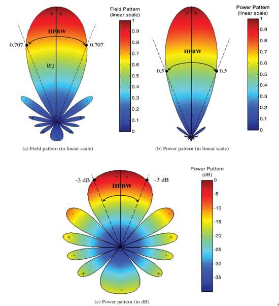
The field and power are usually normalized with respect to their maximum values and are expressed as logarithms (dB). Common radiation patterns:
Field graph (linear coordinates): A graph usually used to show the variation of the electromagnetic field with respect to the spherical space.
Power graph (linear coordinates/dB): The curve of the square of the electric or magnetic field strength with respect to space.
For example, read a relatively important indicator HPBW(Half-Power Beamwidth) half-power beamwidth from the radiation diagram. On the linear coordinate, the voltage is read 0.707, the power is read 0.5, and on the dB coordinate of the power, the -3dB point is read.

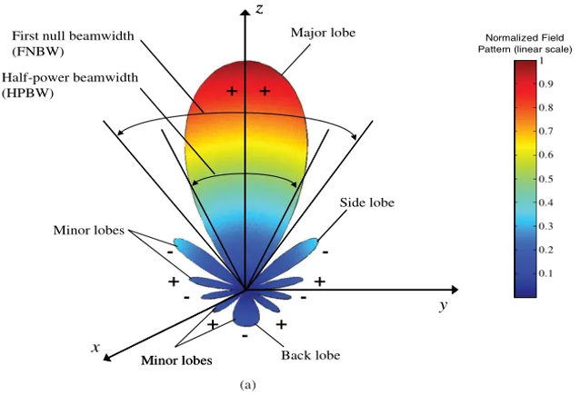
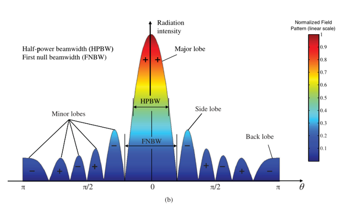
Radiation lobe: The radiation pattern is divided into several regions with the weak radiation intensity as the boundary.
The largest lobes of radiation are called the major lobe and the others are called the minor lobe. The side lobe is usually the lobe with the highest power level. Back lobe is a secondary lobe whose direction is opposite to that of the main lobe.


